

A technical field note from our failure-investigation practice, drawn from recurring patterns rather than any single client or site.
Power-factor correction capacitor banks fail more often than their simplicity suggests. A bank is an unremarkable-looking assembly — rows of individual capacitor units racked together in a substation yard (shown above), wired in series-parallel groups to reach the required voltage and reactive rating. Then a single unit ruptures, an upstream device trips, and part of a facility loses power, often after years of uneventful service. Because the equipment has no moving parts and no obvious wear mechanism, the event is commonly attributed to one worn-out capacitor and cleared by replacement. That conclusion is usually incorrect, and re-energizing on it can reproduce the failure.
This note outlines what a power-factor correction bank does, what the failure evidence typically indicates, and why the cause of a capacitor bank failure usually lies in the system rather than the component.
What a power-factor correction bank does
The governing concept is reactive power. Inductive loads — motors, transformers, chillers — draw current that establishes magnetic fields but performs no useful work. This reactive current (kVAR) adds to the total current the upstream system must carry, raising apparent power (kVA) and lowering the power factor, the ratio of real power to apparent power. A low power factor increases system losses and utility demand charges and consumes transformer and feeder capacity.
A capacitor draws reactive current of the opposite phase — leading rather than lagging. Installed at the facility, a capacitor bank supplies the inductive loads’ reactive demand locally, so that current no longer has to flow from the source. The result is a higher power factor, lower upstream current, reduced penalties, and released capacity. Sizing is deterministic — the required capacitance follows directly from the real load and the initial and target power factors.
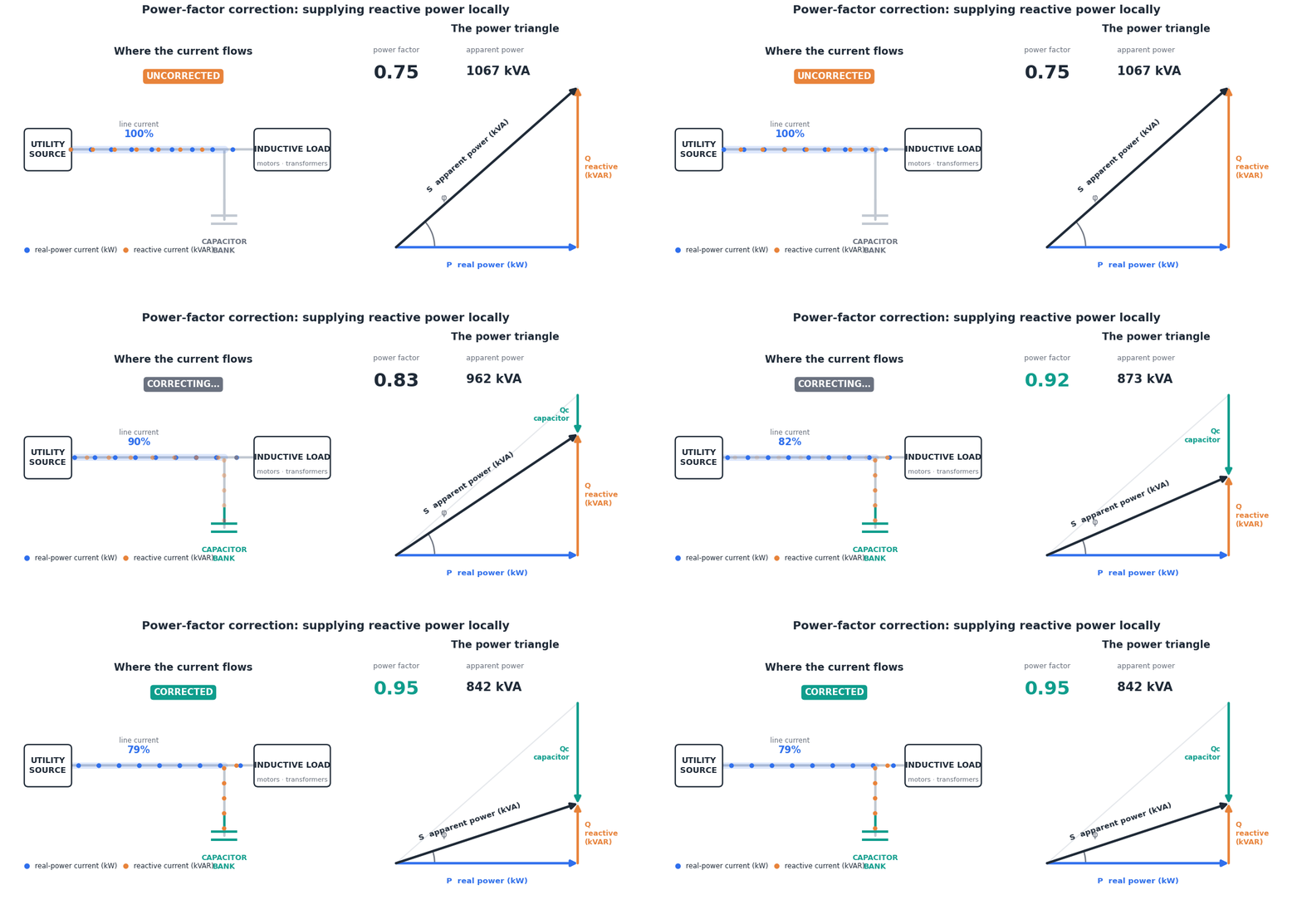
Applied correctly, power-factor correction is a high-return, low-maintenance measure. That reputation is also why its failures tend to be treated as anomalies rather than investigated.
What the failure evidence indicates
The physical evidence often identifies the failure category before any measurement is taken. A ruptured can with adjacent units bulged and thermally discolored points to sustained overstress rather than the abrupt, localized signature of a switching transient. Units still within normal service life argue against dielectric end-of-life. Where the failed units are among the most recently installed — for instance, during a later capacity expansion — age-related failure is effectively excluded.
Each of the remaining mechanisms presents differently. Sustained overvoltage produces its own thermal pattern; a loose or high-resistance connection overheats locally at the joint; a controller that fails to de-energize a stage leaves a different signature again. All are distinguishable on inspection. Determining which mechanism is present — and, more consequentially, what produced it — is the object of the investigation.
Why the cause is usually systemic
The diagnostic question is why particular units failed, and why at that point in the bank’s life. Age does not account for newer units failing beside older survivors, for a heat-driven damage pattern, or for the failure of a bank after years of stable operation.
In these cases the cause is generally not internal to the capacitor. It arises from the interaction between the bank, the source impedance upstream of it, and a facility load whose composition has changed over time — typically as linear machinery is replaced by electronic equipment that draws harmonic current. Each contributing factor is individually unremarkable: every bank expansion may be correctly sized, and every component-level acceptance test may pass. The failure emerges from the combination, which no single-component test evaluates, because the governing condition is a property of the system rather than of any one part.
The specific mechanism is documented in the investigation report. The general principle holds without it: a correction bank can be individually compliant at every stage and still be driven to failure by the system in which it operates.
Practical implication
This pattern is not unique to capacitor banks. Failures in large facilities frequently originate in interactions between correctly functioning components — transfer schemes, paralleled sources, and nominally redundant topologies that share a common element. Component-level testing confirms each part in isolation; it does not evaluate the system those parts form, or how that system changes as loads and sources evolve. Identifying these conditions before they result in equipment failure or loss of load is an analysis task, not a testing one.
MCE provides forensic failure investigation, power-quality analysis, and reliability engineering for mission-critical and large facilities. Contact us to discuss an investigation or system review.

